Are you a
Homeowner?Are you a
Homeowner?The below provides an overview of installation, but please refer to each alarm’s installation manual for tailored guidance.
This heat alarm can be installed in kitchens, utility rooms, boiler rooms, attics and garages. If you’re looking for an alarm for living spaces and hallways and landings, then check out our range of smoke alarms.
The law and recommendation for how many heat alarms are required are specific to the area you live in and your property type.
For the fastest detection of fire we recommend you install a smoke alarm in the circulation space on each level of the home (hallway and landing) as well as in living spaces and bedrooms. We would install these alongside heat alarms in the kitchen, garage and attic and have the alarms interlinked so that if one alarm sounds, they all sound.
Heat alarms are best suited to areas where dust, fumes and moisture can cause nuisance alarms in smoke alarms and should not be used in escape routes instead of smoke alarms.
When heat alarms are installed in a room, they should be placed on the ceiling, ideally in the centre of the room. They should be at a distance no greater than 5.3m from the farthest wall, no greater than 5.3m from a door to any room in which a fire might start and no greater than 5.3m from the next heat alarm.
NOTE: HEAT ALARMS SHOULD NOT BE WALL MOUNTED.
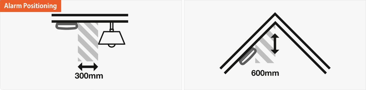
Install at least 300mm from a light fitting or from a nearby wall.
Heat alarms should be positioned at no more than 600mm vertically below the highest point in the room.
WARNING: Wiring should be installed by a qualified electrician in accordance with BS7671. We advise you to follow the new harmonized cable colour coding as specified in BS7671.
IMPORTANT: The circuit used to power the alarm must be a 24 hour voltage circuit that cannot be turned off by a switch. BS 5839: Part 6 states that: For mains powered alarms, each with an integral standby supply (Grade D), the mains electricity supply should take the form of either a) an independent circuit at the dwelling’s main circuit board, in which case no other electrical equipment should be connected to this circuit (other than a dedicated monitoring device installed to indicate failure of the mains electricity supply to the alarms); or b) a separately electrically protected, regularly used local lighting circuit.
Ensure a permanent connection to the fixed wiring of the building is made in a suitable junction box.
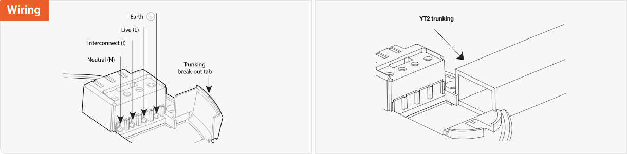
Remove the terminal block cover.
If trunking is required, snap the break-out tab away from the base plate prior to connection.
The wiring must be connected to the terminal block as follows:
Live (L) – Connect to the Live in the house wiring.
Neutral (N) – Connect to the Neutral in the house wiring.
Interconnect (I) – If desired, join the Interconnect wire between the alarms.
Use the Earth terminal to safely terminate any copper Earth or green / yellow cable.
WARNING: Mixing the Live and Neutral connections when interconnecting alarms will damage all the alarms. DO NOT use the Earth wire for the interconnect connection.
Either feed the wire through the hole in the base plate or through the YT2 trunking.
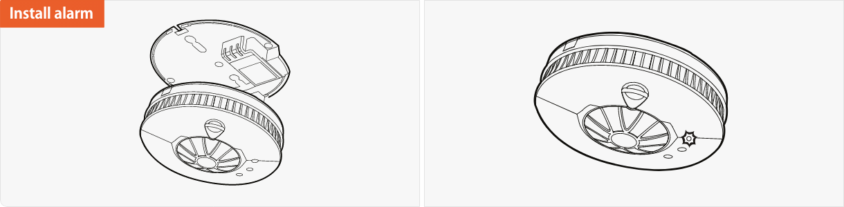
If your alarm is not a sealed back-up battery alarm, then install the batteries following the steps within the manual.
After fitting the alarm to the base plate, wait for 5 seconds for the alarm to settle, then test the alarm. See alarm testing
For guidance on how to hardwire interlink your alarm click here.
If you can't find what your looking for on our blogs and looking for further guidance and advice, our UK-based Customer Support team are on hand all week from 8:30am until 5:30pm, they can answer any further queries you may have on our products, solutions or services.